Frequently Asked Questions (FAQ)
What are the input voltage and rated current limits for this governor?
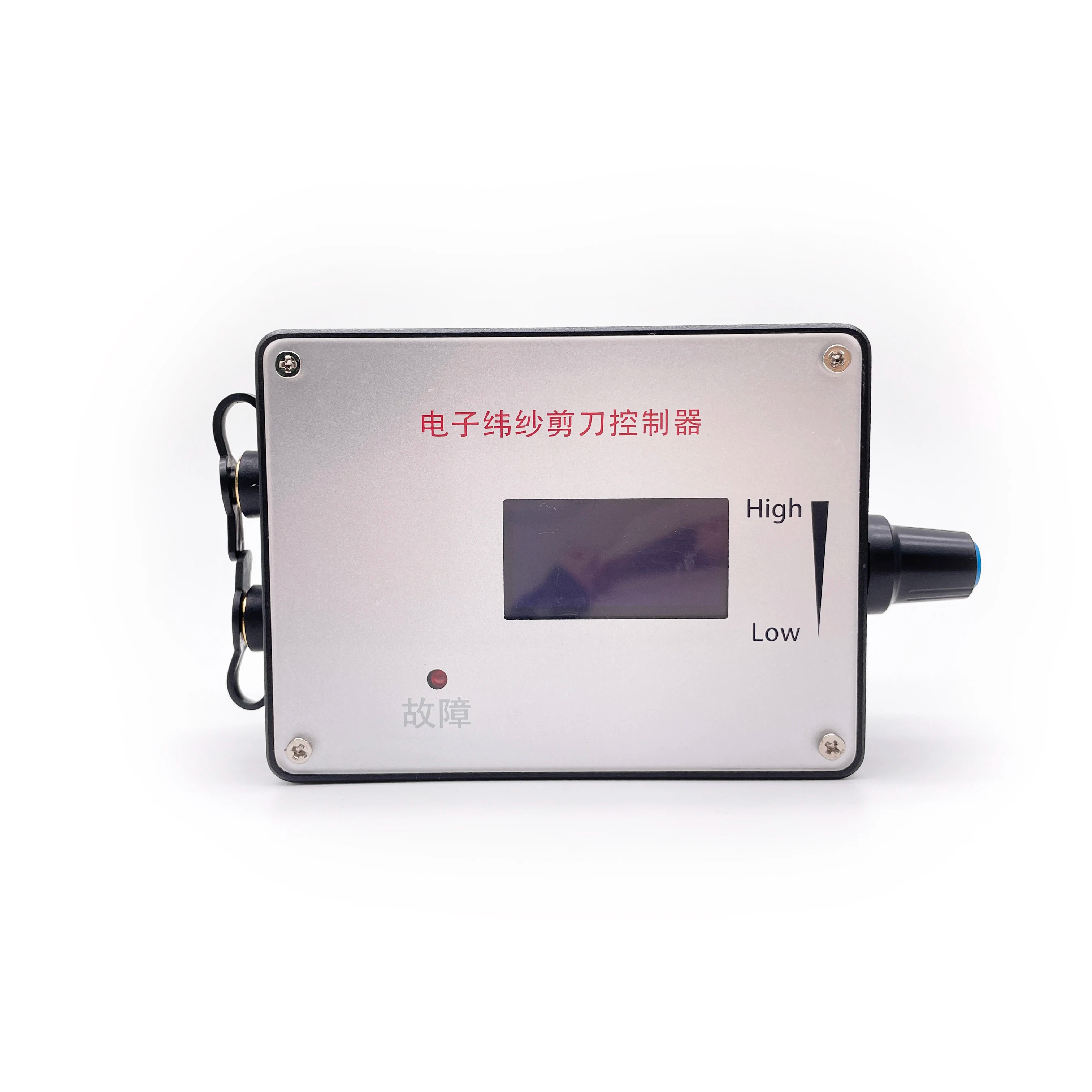
The input voltage range is DC 5V to 28V. The rated current is MAX 2A. If you need to control a motor with higher current requirements, the motor power line must be connected directly to the power supply instead of going through the governor.
How do I adjust the PWM frequency settings on the governor?
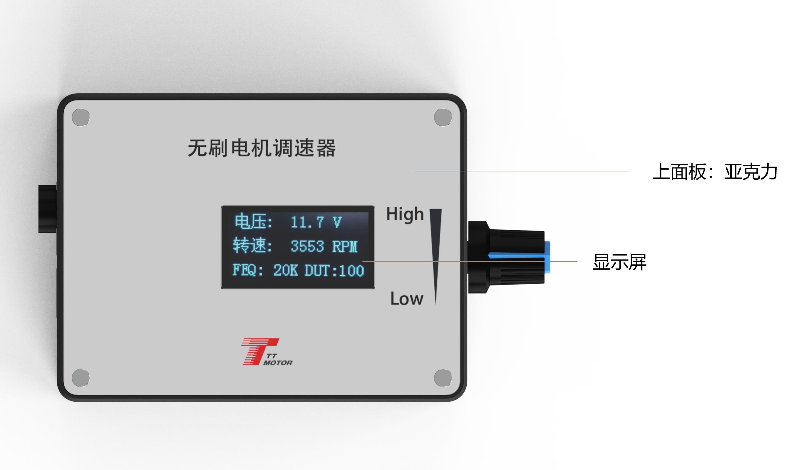
Before powering on the governor board, press and hold touch switch 1. Turn on the power and wait until the screen displays "FEQ:20K" before releasing the button. You can then use touch switch 1 to decrease the frequency or touch switch 2 to increase it. The factory default setting is 20KHz.
How do I configure the number of motor poles on the display?
With the power off, press and hold both touch switch 1 and touch switch 2 simultaneously. Power on the board and release the buttons once the screen shows "number of poles: 1 polarity". Press switch 1 to decrease or switch 2 to increase to match your motor's design (factory default is 1 pole).
What happens if the positive and negative power supplies are reversed?
Reversing the positive and negative power supply connections is highly dangerous. Doing so will prevent the governor from operating and will burn out the internal circuitry of the driver board. Always verify connection polarity before powering on.
How do I set the motor feedback settings (FG vs. FG*3)?
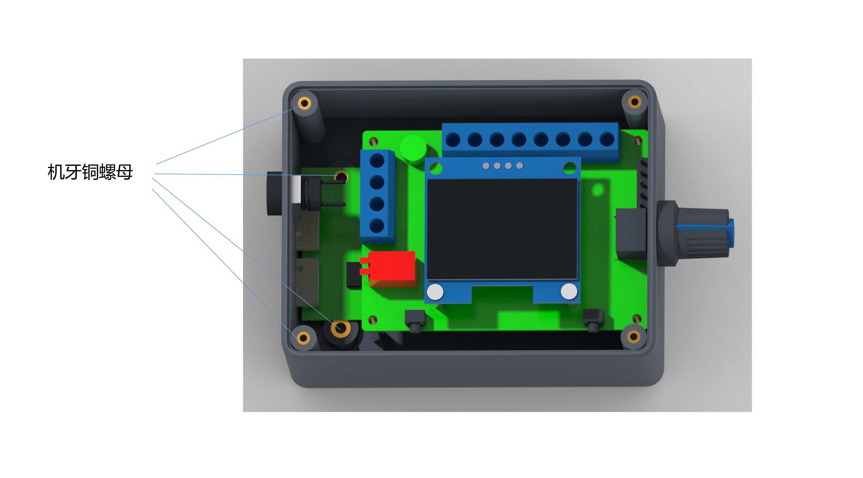
Feedback multiplier configurations are managed via the FG/FG*3 pin jumper cap. Leaving the jumper cap off configures the governor for single times FG feedback, while adding the jumper cap sets it to three times FG (FG*3).
What is the voltage limit for the control interfaces (ports 5 to 9)?
The control interface ports (5 through 9) are designed to handle signal levels. You must ensure that these ports do not access any voltage exceeding 5V.
 RSI Motors