RSI Motors
Choosing the right Miniature Gear Motor is rarely about selecting the smallest motor available. It is about matching torque, speed, voltage, duty cycle, noise, efficiency, and available space. A motor that looks perfect on a datasheet may overheat inside a sealed medical instrument. Small is not simple.
Industry forecasts show why this decision matters. MarketsandMarkets reports continued growth in the global gear motor market, driven by automation, robotics, healthcare equipment, and compact consumer devices. Grand View Research also identifies rising demand for miniature motors in precision applications, including laboratory equipment and advanced manufacturing. These reports indicate strong momentum, but market growth does not guarantee a suitable product for every design. Application conditions still decide performance.
Professor Martin Doppelbauer, an electric-machine researcher at Karlsruhe Institute of Technology, offers a useful engineering reminder: “A motor must be selected for its complete operating point, not its nameplate speed.” That principle supports the ten tips in this guide. Engineers should examine real load profiles, startup torque, backlash, gearbox life, thermal limits, and control requirements. They should also request measured data, not vague claims such as “high efficiency” or “low noise.”
There is room for caution. Published ratings may use different test methods, making direct comparisons imperfect. A 12-volt Miniature Gear Motor may perform well in a laboratory, yet struggle after thousands of repeated cycles. Check the details. Ask better questions. Then choose the motor that survives the actual machine, not merely the specification sheet.
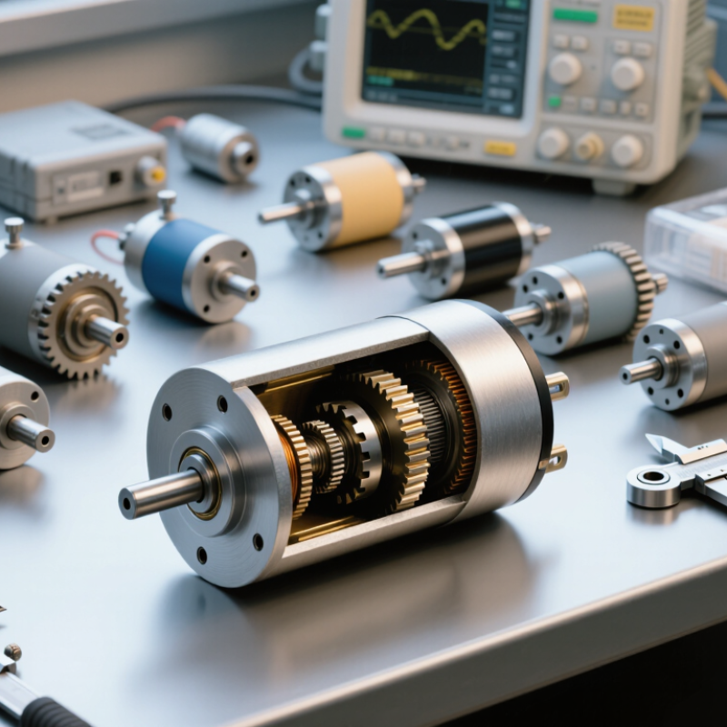
Before choosing a miniature gear motor, define what the mechanism must do. Record the required speed, torque, voltage, direction, and operating time. A small motor may turn a light sensor easily but stall under a tight belt or sudden load.
Write down the real conditions.
Measure the starting load, not only the running load. Check whether the motor must start against friction, gravity, or a spring. Then estimate continuous torque and peak torque separately. Leave a practical safety margin, usually based on measured data rather than optimistic calculations. I have seen designs work perfectly on a bench and fail after assembly because the gearbox faced extra shaft pressure. That mistake is easy to repeat.
Environment matters just as much. Note the available space, mounting position, temperature, dust, moisture, and vibration. Confirm the power supply during startup, because voltage drops can reduce torque and create erratic movement. For frequent reversing, examine backlash, gear wear, and control response. For long duty cycles, check heat buildup every few minutes during testing. An unloaded test is not enough. Use the actual shaft, coupling, and working load whenever possible. If the requirements are uncertain, record assumptions and test them one at a time. A slightly slower motor may prove more reliable, although that choice can feel disappointing during early design reviews.
A practical specification guide for matching a miniature gear motor to the mechanical load, electrical supply, duty cycle, and environmental conditions.
| Tip | Application Requirement | Typical Requirement Definition | Why It Matters When Selecting a Miniature Gear Motor |
|---|---|---|---|
| 1 | Define the Driven Load |
Load type: conveyor roller Required output torque: 0.15 N·m Starting torque: 0.30 N·m |
Calculate both running and starting torque. The motor and gearbox should provide sufficient starting torque without operating continuously at their maximum rated output. |
| 2 | Set the Required Output Speed |
Target output speed: 60 rpm Acceptable operating range: 50–70 rpm Speed variation allowed: ±10% |
Output speed depends on motor speed, gear ratio, load, and voltage. Choose a reduction ratio that reaches the target speed under the actual working load, not only at no load. |
| 3 | Calculate the Power Requirement |
Output torque: 0.15 N·m Output speed: 60 rpm Mechanical output power: approximately 0.94 W |
Mechanical power can be estimated with P = T × ω. Include gearbox and motor losses when determining the electrical input power and the suitable motor size. |
| 4 | Confirm the Voltage and Current Supply |
Available supply: 12 V DC Continuous current budget: 0.8 A Short-duration startup current: up to 2.0 A |
Verify the nominal voltage, continuous current, startup current, and driver capacity. A power supply that cannot handle startup current may cause stalling, resets, or unreliable starting. |
| 5 | Specify the Duty Cycle |
Operating pattern: 30 seconds on, 90 seconds off Duty cycle: 25% Required service life: 2,000 operating hours |
State whether operation is continuous, intermittent, or cyclic. Duty cycle affects winding temperature, allowable torque, thermal recovery time, and expected gear life. |
| 6 | Evaluate Starting and Reversing Conditions |
Starts per hour: 120 Direction changes: 20 per hour Load during start: 100% of rated load |
Frequent starts, stops, braking, and reversals increase thermal and mechanical stress. Confirm the gearbox, bearings, commutation system, and controller are suitable for the switching frequency. |
| 7 | Check Mechanical Interface Requirements |
Available motor diameter: 25 mm maximum Maximum motor length: 45 mm Output shaft: 4 mm diameter, D-flat Mounting: two-hole flange |
Compare the motor envelope, mounting pattern, shaft diameter, shaft length, gearhead orientation, and allowable radial or axial loads with the available installation space. |
| 8 | Account for Environmental Conditions |
Ambient temperature: 0–40 °C Relative humidity: up to 80%, non-condensing Exposure: light dust, no direct water spray |
Temperature, humidity, dust, chemicals, and water exposure influence insulation, lubrication, corrosion resistance, sealing, and the required protection level of the motor assembly. |
| 9 | Determine Noise, Vibration, and Backlash Limits |
Maximum acceptable sound level: 55 dB(A) at 1 m Positioning application: required Permitted output backlash: up to 2° |
Spur, planetary, and worm gear systems have different efficiency, noise, backlash, and self-locking characteristics. Select the gear technology according to motion quality and positioning accuracy. |
| 10 | Allow a Practical Safety Margin |
Calculated continuous torque: 0.15 N·m Suggested design target: at least 0.20 N·m Thermal and load margin: approximately 25–35% |
Include reasonable margin for friction changes, supply variation, production tolerances, aging, temperature rise, and unexpected load peaks. Avoid excessive oversizing, which can increase cost, current draw, and physical dimensions. |
Note: The values shown are application examples for preliminary selection. Final sizing should be verified with the actual load profile, mounting arrangement, ambient conditions, controller settings, and motor test data.
Record speed, torque, voltage, direction, duty cycle, and operating time. Test the real load. Include starting friction, gravity, springs, belts, and sudden resistance. A small motor may turn freely but stall after assembly.
Starting torque must overcome friction and acceleration. Running torque keeps the mechanism moving. Peak torque can occur briefly during reversal or impact. Use measured values and add a practical safety margin.
Spur gears suit simple systems with moderate loads and lower costs. Planetary gears provide higher torque in compact spaces. Worm gears offer strong reduction and holding resistance. They usually create more heat and lose more energy.
Measure the available space, output shaft, mounting holes, and cable clearance. Check the lever length, acceleration, friction, and load. A motor can fit physically but still fail mechanically. This detail is easy to miss.
Hardened steel suits repeated loads and resists tooth wear. Polymer gears reduce noise and weight. Heat and shock may shorten their service life. Brass can run smoothly but may wear faster under heavy pressure.
Check voltage tolerance, startup current, and driver capacity under real load. Startup current may be several times higher than running current. Voltage drops can reduce torque and cause uneven movement. Measure the supply during acceleration, not only at rest.
Listen during startup, steady motion, and reversal. Clicking may indicate backlash or poor alignment. A high-pitched whine may involve gear mesh or switching. Measure sound from one metre away using the same mounting surface. Check temperature after thirty minutes.
Load, temperature, lubrication, duty cycle, and reversing frequency all matter. Frequent reversals may stress gears more than continuous motion. Keep a simple log of temperature, noise, load, and failures. Do not assume slower speed always means longer life. That assumption needs testing.
Choosing the right Miniature Gear Motor begins with clearly defining the application, including load requirements, available space, duty cycle, speed, temperature, and environmental conditions. The motor’s output speed and torque should match the mechanism, while the gear ratio must provide a suitable balance between movement, force, and responsiveness. It is also important to select a gearbox type and size that can withstand the expected load, with transmission materials chosen for durability, weight, and operating conditions.
Before making a final decision, evaluate the available power supply, energy efficiency, operating noise, heat generation, and expected service life. Confirm that the motor supports the required mounting arrangement and offers suitable control features, such as speed adjustment or position feedback when needed. Consistent manufacturing quality, reliable testing, clear technical documentation, and responsive supplier support can further reduce installation problems and long-term maintenance costs. A careful comparison of these factors helps ensure dependable performance and a practical fit for the complete system.