A small actuator can move a camera, open a valve, or position a packaging guide with surprising precision. Add a gearbox, and the motor can deliver more torque at a lower output speed. That combination is called a Stepping Gear Motor. It pairs a stepper motor’s controlled, incremental rotation with gears that change the output’s speed and force.
The wider motor industry shows why these components matter. The International Energy Agency’s 2011 report, Energy-Efficiency Policy Opportunities for Electric Motor-Driven Systems, estimated that motor-driven systems used about 45% of global electricity. That figure covers many motor types, not stepping gear motors alone. Still, it highlights the value of choosing a motor system that fits its actual task. A motor that is oversized, poorly matched, or run inefficiently can waste energy and complicate control.
How does a stepping gear motor work? The controller energizes the motor’s coils in a sequence, moving its rotor through measured steps. Gears then reduce rotational speed and increase torque at the output shaft. Precision matters. Yet step count alone does not guarantee exact positioning: load, friction, backlash, and missed steps can all affect real-world performance. There is no universal best configuration, which can make selection frustrating. In this guide, we’ll explain the motor’s parts, operating principle, benefits, and limits, then outline what to consider when matching one to an application. The details matter.
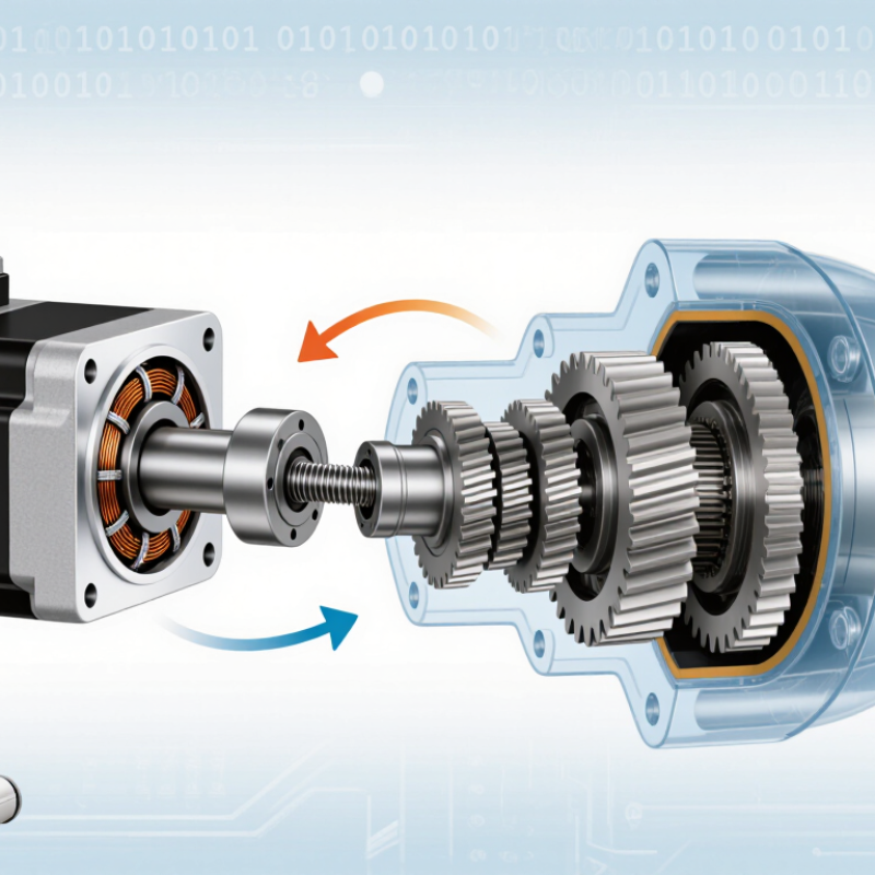
What a Stepping Gear Motor Is
A stepping gear motor is a stepper motor paired with a reduction gearbox. The motor turns in measured increments when its controller sends electrical pulses. The gearbox then reduces output speed and increases available torque. Together, they can move a load in small, repeatable steps without requiring a separate gear unit.
Inside the motor, energized coils create a changing magnetic field that moves a rotor from one position to the next. The gearbox passes that motion through gears, so the output shaft turns more slowly than the rotor. For example, a small motor may make several internal turns while a platform advances only a few degrees. This helps with tasks such as positioning a camera mount, adjusting a valve, or feeding material through a compact mechanism. Small steps matter.
The term can be a little loose: gear ratio, step angle, and gearbox play all affect actual movement. A higher ratio may provide more torque, but it also lowers output speed. Small amounts of backlash can appear when the direction changes, especially in inexpensive or worn gear sets. For a real application, check the load, duty cycle, mounting space, and required positioning accuracy rather than relying on motor torque alone. The numbers on a datasheet do not always tell the whole story.
The Main Components Inside a Stepping Gear Motor
Inside a stepping gear motor, the stepper section and gearbox work as one assembly.
The stator contains copper coils arranged around a toothed core. When a driver energizes these coils in sequence, their magnetic fields pull the rotor from one position to the next. Many designs use a permanent-magnet or hybrid rotor, with fine teeth that help control movement.
Small parts matter.
A central shaft carries the rotor’s motion into the gearbox. Inside, compact gears—often spur or planetary gears—reduce output speed and increase available torque. The exact arrangement depends on the motor’s size and intended load. Bearings support rotating shafts, while a metal or reinforced housing keeps the gears aligned.
A slight alignment error can add noise or wear.
Gear reduction has a trade-off.
It can make a small motor more useful for turning a loaded mechanism, but it does not create power; friction and gear losses reduce efficiency. The gearbox may also introduce backlash, a small amount of movement when direction changes. During inspection, look for smooth shaft rotation, secure mounting, and signs of grease leakage. These checks help, though they cannot reveal every internal wear issue.
How Electrical Pulses Produce Step-by-Step Motion
A stepping gear motor turns electrical pulses into controlled rotation. A driver sends timed current pulses through stator windings, changing their magnetic poles. The rotor moves to align with each new magnetic field. Each pulse produces a small, defined step. The sequence matters: reverse it, and the shaft reverses too.
In a common 1.8-degree hybrid stepper, 200 full steps turn the motor shaft once. Add a 5:1 gearbox, and the output advances about 0.36 degrees per full step, ideally. Small moves, repeated. Microstepping can divide each commanded step further, but it does not guarantee matching accuracy; load, friction, and gearbox backlash all intervene. That part is easy to overlook. The U.S. Department of Energy’s 2002 United States Industrial Electric Motor Systems Market Opportunities Assessment estimated that motor systems used 63% of U.S. industrial electricity. That figure covers many motor types, not just steppers, but it shows why controlled motion and efficient drive choices matter. In practice, engineers check pulse rate, current limits, and load inertia together; a motor that steps cleanly on the bench may vibrate or miss steps under a real load.
What Is a Stepping Gear Motor and How Does It Work? - How Electrical Pulses Produce Step-by-Step Motion
| Aspect |
How It Works |
Practical Effect |
| Stepper motor |
Electrical pulses switch current through the motor windings, creating magnetic fields that move the rotor through defined angular steps. |
The number of command pulses determines the motor’s commanded position; pulse frequency determines its commanded speed. |
| Full-step angle |
Many two-phase hybrid stepper motors use a 1.8° full-step angle, equivalent to 200 full steps per motor revolution. |
This is a common example, not a universal specification; the motor’s datasheet defines its actual step angle. |
| Gearbox and ratio |
A gear train connects the motor shaft to the output shaft. For a 5:1 reduction, the motor turns five times for one output-shaft revolution. |
Reduction lowers output speed and, ideally, increases output torque in proportion to the ratio; real torque is lower because of gearbox losses. |
| Illustrative output step |
With a 1.8° motor and a 5:1 reduction, the ideal output movement per full motor step is 1.8° ÷ 5 = 0.36°. |
Actual positioning can be affected by gearbox backlash, mechanical compliance, load, and stepper-motor accuracy. |
| Pulse frequency and speed |
For a fixed step mode and gear ratio, increasing the pulse rate increases the commanded shaft speed. A driver may also divide each full step into microsteps. |
Microstepping can make motion smoother, but commanded microstep size is not the same as guaranteed positioning accuracy. |
| Direction control |
A stepper driver changes the order in which winding currents are energized to reverse the rotating magnetic field. |
The motor can move in either direction without changing the gearbox, subject to the application’s mechanical limits. |
| Holding and missed steps |
When energized, the motor can produce holding torque at a stationary position. If the required load or acceleration exceeds available torque, it may lose synchronism. |
Many open-loop systems do not detect missed steps automatically; suitable sizing and controlled acceleration help maintain position. |
| Typical applications |
Stepping gear motors are used where controlled low-speed motion and increased output torque are useful, such as positioning mechanisms, feeders, and small automation systems. |
Selection should account for required torque, speed, duty cycle, backlash, mounting, and the motor-driver power requirements. |
Values shown are illustrative; actual step angle, gear ratio, torque, speed, and positioning performance depend on the specific motor, gearbox, driver, and load.
How the Gearbox Changes Speed and Torque
A stepping gear motor combines a stepper motor with a gearbox. The motor moves in fixed increments, while the gearbox changes how those movements reach the output shaft. Its gear ratio determines the main trade-off: lower output speed in exchange for greater torque.
With a 10:1 reduction, the output shaft turns once for every ten motor turns. Output torque can rise by roughly ten times before gearbox losses, though real performance is lower. The gearbox also makes each motor step produce a smaller movement at the output. That can improve positioning resolution. Not magic. Gear clearance, called backlash, may still cause a small amount of movement when direction changes.
Imagine a small turntable carrying a load. A suitable reduction may help it start smoothly and resist the load without demanding as much torque directly from the motor. But the gearbox adds friction, size, and inertia. It can also limit the system’s maximum speed. A common mistake is choosing a high ratio based only on torque. Check the required output speed, load, and positioning accuracy together. I’d also leave some margin; calculated torque rarely tells the whole story.
How a Gearbox Changes Speed and Torque
This illustrative comparison assumes a stepper motor running at 300 RPM and producing 0.20 N·m, with gearbox efficiency held at 80%. Increasing the reduction ratio lowers output speed and increases estimated output torque. Actual performance depends on the motor’s operating conditions and the gearbox’s efficiency and torque rating.
Common Uses and Key Selection Factors
A stepping gear motor combines a stepper motor with a reduction gearbox. The motor moves in discrete electrical steps, while the gears trade speed for greater output torque. This makes the motor useful for compact indexing tables, label feeders, small conveyors, camera sliders, and laboratory dosing equipment. Positioning can be repeatable without an encoder, but overload may cause missed steps. Not magic.
Choose a motor by starting with the load, not the catalog torque figure. Estimate continuous and peak torque, output speed, acceleration, duty cycle, and reflected inertia. Then check gear ratio, backlash, shaft dimensions, driver current, noise, and heat.
The International Federation of Robotics’ World Robotics 2024 report recorded 541,302 industrial robot installations worldwide in 2023.
That figure describes automation broadly, not stepping gear motors specifically, but it shows the scale of demand for controlled motion. Test under the real load and operating temperature, then verify positioning over repeated cycles.
A generous torque margin helps, yet excessive reduction can slow throughput and increase backlash. Gearbox wear can also shift performance over time.
Conclusion
A Stepping Gear Motor combines a stepper motor with a gearbox to provide controlled movement and useful turning force. Its main components typically include a stator with coils, a rotor, a drive shaft, and a gear train housed in a compact enclosure. When the motor receives electrical pulses in a chosen sequence, its magnetic field shifts, moving the rotor through precise increments. By controlling the pulses, a system can adjust the motor’s position and speed.
The gearbox reduces output speed while increasing torque, helping the motor handle loads that a stepper motor alone may not manage as effectively. Stepping Gear Motors are used in equipment that needs measured, repeatable motion, such as positioning mechanisms and small automated devices. When selecting one, consider the required torque, speed, step accuracy, load, available space, power supply, and operating conditions. These factors help ensure the motor and gearbox suit the task.
 RSI Motors