RSI Motors
Choosing a Single Phase Gear Motor is not simply a matter of matching voltage and shaft speed. The correct choice begins with the machine’s real workload. Measure starting torque, running torque, operating hours, and required output speed. A conveyor carrying uneven boxes needs different protection from a small packaging feeder.
Austin Hughes, author of Electric Motors and Drives, expresses a practical principle: “The motor must be selected to suit the load, not the other way around.” That idea remains useful. A larger motor may appear safer, but it can waste energy, increase starting stress, and overload the gearbox. A smaller unit may stall beside a warm, humming conveyor.
Look closely at the details.
Check the available supply, usually 115 or 230 volts, and confirm the motor’s rated frequency. Compare the gearbox ratio with the required shaft speed. Then examine torque at startup, not only torque during normal operation. For dusty rooms, washdown areas, or outdoor equipment, the enclosure rating deserves equal attention. Poor sealing can ruin a reliable motor quickly.
Duty cycle also matters. A Single Phase Gear Motor running for ten minutes differs from one operating continuously for sixteen hours. Thermal protection, lubrication, mounting position, brake requirements, and noise limits should enter the decision. Real installations are rarely perfect. Measurements may be incomplete, and catalog data can be misunderstood. That is why a careful selection should include a small safety margin, manufacturer verification, and testing under the actual load. The best Single Phase Gear Motor is not the most powerful model. It is the one that delivers stable motion, acceptable heat, and dependable service without paying for unnecessary capacity.
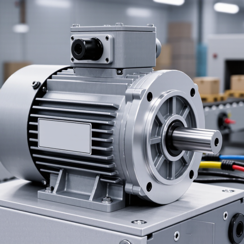
Choosing a single phase gear motor starts with the application, not the catalog. Identify the driven load, required speed, starting torque, and operating cycle. A conveyor moving 40 kilograms may need high starting torque, even when its running speed is modest. Measure twice.
Record the output speed in revolutions per minute and calculate the needed torque at the shaft. Include friction, incline, belt tension, and unexpected load changes. A motor that runs smoothly without a load may stall when a container reaches the end stop. This detail is easy to miss. Confirm the gear ratio, shaft orientation, mounting position, and available space before selecting the motor.
Operating conditions also shape the specification. Check ambient temperature, humidity, dust, washdown exposure, and ventilation. A motor inside a warm, enclosed cabinet may require more thermal capacity than one in open air. Define the duty cycle clearly, such as ten starts per hour or continuous operation. Frequent starts can produce more heat than steady running. For safer selection, compare the calculated requirement with the motor’s rated performance, then allow a practical margin without excessive oversizing. Oversizing can increase cost and starting stress. I have seen installation drawings omit cable length and voltage fluctuations, both of which can affect real performance. Recheck these conditions with the equipment operator before ordering.
Choosing the right single-phase gear motor starts with four numbers: power, torque, speed, and gear ratio. Measure the driven load, not only its advertised wattage. The IEA reports that electric motor systems consume about 46% of global electricity and 69% of industrial electricity (Energy-Efficiency Policy Opportunities for Electric Motor-Driven Systems, 2011). Small sizing errors become costly during long operating cycles. Calculate torque with T = 9550 × P ÷ n. Here, P is kilowatts and n is output speed in revolutions per minute. A 0.75 kW motor at 60 rpm produces roughly 119 Nm before losses. Include gearbox efficiency, starting resistance, and a service factor.
Gear ratio trades speed for torque. A 1,400 rpm motor driving a 70 rpm shaft needs a nominal 20:1 ratio. Check peak torque during jams, cold starts, and uneven loading. Also review rated torque, locked-rotor behavior, duty class, thermal rise, and capacitor arrangement. A single-phase motor may start poorly under heavy inertia, even when running power seems adequate. That detail is often missed.
Test the system under real conditions. Use a tachometer, estimate torque, and compare current with the nameplate value. Inspect temperature after several cycles. A neat spreadsheet can still lie. Voltage drop, lubricant temperature, and frequent reversals change performance. The U.S. Department of Energy recommends evaluating the motor, gearbox, controls, and load as one system (Improving Motor and Drive System Performance, 2014).
| Typical Application | Rated Power (W) |
Input Voltage (V AC) |
Output Speed (rpm) |
Gear Ratio | Typical Output Torque (N·m) |
Approx. Output Power (W) |
Selection Guidance |
|---|---|---|---|---|---|---|---|
| Light-duty conveyors and small fans | 90 | 110–120 / 220–240 | 45–60 | 25:1–35:1 | 10–14 | 55–70 | Choose when the load is continuous but has low starting resistance and limited shock loading. |
| Compact mixers and indexing equipment | 180 | 110–120 / 220–240 | 30–45 | 35:1–50:1 | 28–40 | 140–160 | Use additional torque margin if the machine must start under load or accelerate frequently. |
| Packaging machines and small hoists | 370 | 110–120 / 220–240 | 20–35 | 50:1–75:1 | 90–130 | 280–330 | Verify the brake, shaft load, and duty cycle when stopping or holding a suspended load. |
| Heavy-duty conveyors and agitators | 750 | 220–240 | 15–25 | 60:1–100:1 | 250–420 | 560–680 | Select a larger service factor for high-inertia loads, frequent reversing, or intermittent shock loads. |
| Low-speed screw feeders and actuators | 1,100 | 220–240 | 8–15 | 100:1–180:1 | 650–1,100 | 850–980 | Check thermal capacity, lubrication, mounting orientation, and allowable radial or axial shaft loads. |
Selecting the correct gearbox type starts with the machine’s torque, speed, and operating pattern. A worm gearbox suits compact equipment and right-angle drives. It also offers useful holding resistance when the load tends to back-drive the shaft. However, it can generate more heat and waste energy during continuous operation. Helical gearboxes usually provide better efficiency and smoother transmission. Parallel-shaft designs work well when space is limited around the motor.
Efficiency matters. For repeated lifting or conveyor service, compare rated torque with the actual load and duty cycle. Check the service factor, output speed, thermal limits, and starting requirements of the single-phase motor. A gearbox that works briefly may fail during eight-hour operation. That detail is easy to miss.
Mounting design deserves equal attention. Foot mounting provides a stable base for a flat frame. Flange mounting saves space and keeps the gearbox close to the driven machine. Hollow-bore mounting can reduce coupling parts, but shaft alignment must remain precise. Measure the shaft diameter, keyway, bolt pattern, and available clearance before ordering. Keep the output shaft supported when side loads are present.
I once focused too much on torque and overlooked the mounting direction. That choice caused awkward cable routing and difficult maintenance. Now I verify installation drawings, lubrication access, and drain position early. Ask whether the gearbox can tolerate the real radial and axial loads. Do not rely on nominal torque alone.
Choosing a single phase gear motor starts with electrical compatibility. Confirm the rated voltage, frequency, phase, capacitor value, and full-load current. A 230 V motor may run poorly on an unstable 220 V supply. Check the nameplate and measure the actual voltage at the motor terminals. Cable length can create a surprising drop.
Duty cycle is equally important. S1 means continuous operation, while S3 describes intermittent running with defined rest periods. A conveyor running eight hours daily needs different thermal capacity than a gate actuator moving for thirty seconds.
The U.S. Department of Energy reports that motor-driven systems consume more than 70% of industrial electricity. Small selection errors can therefore become expensive.
Add overload protection, especially when the gearbox starts under load. It is often overlooked.
Efficiency must be judged across the real operating range, not only at the rated point. The International Energy Agency has reported that motor systems use roughly half of global electricity, making efficient selection commercially meaningful.
Compare motor efficiency with gearbox efficiency, starting torque, and expected load. A smaller motor may consume less power but overheat during repeated starts. That choice can look efficient on paper. In practice, it may fail early. Record running temperature, current, and cycle time during a trial installation. Then reconsider the selection if the measured figures differ from the catalogue data.
Choosing a single phase gear motor starts with its working environment, not its catalog power rating. Check the enclosure protection rating against dust, splashing water, washdown routines, and installation height. A higher rating can reduce contamination risks, but it may increase heat retention and purchase cost. Measure the actual load, starting torque, duty cycle, and ambient temperature before selecting the motor. Real measurements beat assumptions.
Maintenance planning should be practical for a technician working beside a noisy conveyor. Ask whether bearings are serviceable, terminals are accessible, and replacement parts can be sourced reliably. Inspect seals, cable entries, fasteners, and unusual vibration during scheduled checks. Keep a simple log of temperature, noise, current, and lubricant condition. Many gear motors fail from misalignment or poor mounting, rather than dramatic overload. That detail is easy to miss. A sealed design may reduce routine attention, but it does not remove inspection needs. I once treated “maintenance-free” as “check-free.” That was an expensive misunderstanding.
Compare total cost across the service life, including energy use, downtime, installation labor, spare parts, and disposal. A cheaper motor can become costly after repeated stoppages or difficult access. Estimate the cost of one hour of lost production. Then test realistic scenarios, including overloads and cold starts. Do not choose protection or maintenance features by habit. Operating conditions often change after installation.
Identify the load, output speed, starting torque, and operating cycle. Measure twice. Include friction, incline, belt tension, and sudden load changes.
A conveyor carrying 40 kilograms may start under heavy resistance. The motor can run smoothly unloaded, then stall at the end stop. That detail is easy to miss.
Check temperature, humidity, dust, washdown exposure, and ventilation. An enclosed cabinet may trap heat around the motor. Frequent starts can create more heat than steady running.
A worm gearbox suits compact equipment and right-angle drives. It can resist back-driving when the load tends to reverse the shaft. However, it may lose more energy during continuous operation.
Helical gearboxes usually provide smoother transmission and better efficiency. Parallel-shaft designs help when side space is limited. Compare torque, speed, thermal limits, and operating duration.
Foot mounting suits a stable, flat frame. Flange mounting keeps the gearbox close to the driven machine. Hollow-bore mounting can reduce coupling parts, but alignment must remain precise.
Confirm voltage, frequency, phase, capacitor value, and full-load current. Measure voltage at the motor terminals. Long cables can cause an unexpected voltage drop.
Continuous operation needs different thermal capacity from a thirty-second actuator cycle. S1 indicates continuous running, while S3 indicates intermittent operation with rest periods. Add suitable overload protection.
Record running temperature, current, and cycle time during a trial installation. Compare these readings with the calculated requirements. Catalogue data may look perfect. Reality sometimes disagrees.
Choosing the right Single Phase Gear Motor begins with clearly defining the application requirements and operating conditions. Consider the required load, starting force, running speed, operating environment, and available installation space. Compare the motor’s power and torque with the actual demands of the equipment, and select a suitable gear ratio to achieve the desired output speed and performance without overloading the system.
Next, evaluate the gearbox type and mounting design to ensure proper alignment and easy installation. Confirm that the motor’s voltage, frequency, current, and control method are electrically compatible with the system. Duty cycle and energy efficiency should also match the intended usage to prevent overheating and unnecessary operating costs. Finally, review protection ratings, maintenance requirements, service accessibility, expected lifespan, and overall ownership cost. A well-selected Single Phase Gear Motor should provide reliable operation, efficient power transmission, straightforward maintenance, and long-term value for the application.
